
Sustainable Manufacturing and Foundry Practices


1Defence Metallurgical Research Laboratory, Hyderabad, Telangana, India
2National Institute of Technology Jamshedpur, Jharkhand, India

This article is distributed under the terms of the Creative Commons Attribution-NonCommercial 4.0 License (https://creativecommons.org/licenses/by-nc/4.0/) which permits non-commercial use, reproduction and distribution of the work without further permission provided the original work is attributed as specified on the SAGE and Open Access page (https://us.sagepub.com/en-us/nam/open-access-at-sage).
The pyro housings of the propulsion systems of three different anti-tank missiles were damaged during flight testing and received in damaged condition. Failure investigations were undertaken with the help of visual observation, optical microscopy, scanning electron microscopy, hardness testing, glow discharge optical spectroscopy, and optical emission spectroscopy to assess the reason for the failure of these components. Results indicated that all pyro housings were made from Al alloy HF15 grade (24345) and used in T6 heat-treated condition. The pyro housing of one missile failed, as the groove was longer and had a higher angle of inclination. This makes the groove thinner with reduced load-bearing capacity. There was improper manufacturing by closed-die forging of the other two pyro housings. This resulted in elongated grains in certain directions and lower load-bearing capacities. There was no metallurgical deviation from the recommended material and composition.
Anti-tank missile, propulsion system, failure analysis, booster head
Introduction
An anti-tank missile having an imaging infrared seeker for a guidance system is used extensively in most warfare. These missiles have the striking capability of armoured vehicles located 4-7 km away. These missiles carry tandem warheads to strike main armour and explosive reactive armor. These missiles can be deployed on a land vehicle or rotorcraft.
Failure analysis of propulsion systems, particularly solid propulsion systems, has been carried out earlier (Jha et al., 2011, 2013). Jha et al. (2011) investigated the failure reason of a stud made of maraging steel used in the flex nozzle control actuator bracket of a solid propulsion system. They found that the synergistic effect of stress and corrosion is responsible for the failure of the component. According to Jha et al. (2013), maraging steel fasteners used in the nozzle assembly of a solid propulsion system failed because of a similar reason. Several articles are available on the failure of domes (Bayraktar et al., 2022; El-Mahdy et al., 2025; Foraboschi, 2014). These domes are primarily civil structures. Failure of domes of pyro housing is not reported. Analysis of failure of various missile components has been carried out previously (Kim et al., 2005; Madhav & Roy, 2025; Schulz & Moran, 2001). It was found that the crack in the rocket motor of the interceptor missile was generated under the simultaneous action of corrosion and stress and propagated through grain boundaries (Kim et al., 2005). Failure of the pin locator was found to be because of the generation of intergranular quench cracking (Madhav & Roy, 2025). The missile fin of another system was found to fail due to cyclic loading by a fatigue crack, as confirmed by striation marks (Schulz & Moran, 2001). Failure investigation of domes of pyro housing of propulsion systems of missiles is not available at all in the literature. These facts prompted us to undertake the proposed work on the metallurgical investigation of failed parts of the propulsion system of the anti-tank missile.
In the present work, it was noted that the booster head of the propulsion system of an anti-tank missile was damaged. In another missile, it was found that the hot gases were directed toward the blast tube, resulting in the melting away of part of the dome of the propulsion system. The gas flow directed toward the centre melted away the aluminium (Al) alloy casing of the blast tube on one side up to half of the length in the propulsion system of another missile. Metallurgical investigations were carried out for all the failed components, and the results of the investigations are analysed in detail in the present article.
Background
The pyro housing, as an integral part of the booster head pertaining to the propulsion system of an anti-tank missile, was received in a damaged condition. This part is termed ‘PH-1.’ The booster head end is an enclosure for booster motor functioning for 1.4 s at a chamber pressure of 50 Ksc. Metallurgical investigation of the failed component is carried out in detail. The failed rear dome of the pyro housing of another missile designated as PH-2 was also brought for investigation. Another missile exhibited a defective dome of the pyro housing of the propulsion system. This part was designated as PH-3. Both these failed parts were examined extensively to assess the cause of the failures.
Investigations
All the failed components were visually examined with necessary care and details. Samples were cut close to the fracture surface and away from the fracture surface, hot mounted, and polished progressively on emery paper up to 600-grit polishing, followed by cloth polishing. Samples were then viewed under an optical microscope in etched and unetched conditions. Etching was done with Keller’s reagent. Hardness of the samples was measured with a Vickers indenter at a 5-kg load. The loading and unloading time was 10 s, and the holding time was 15 s. The chemical analysis of the pyro housings was carried out by instrumental analysis employing glow-discharge optical spectroscopy and optical emission spectroscopy. A glow-discharge optical spectrometer was used at a discharge voltage of 1,000 V and a discharge current of 50 mA. The pressure of argon gas was around 5 Torr. Optical emission spectroscopy was operated with high-purity argon gas with an inlet pressure of approximately 5 bar, with a high-voltage spark discharge up to 10,000 V and a frequency between 100 and 1,000 Hz. The failed samples were cut carefully so as not to damage the fracture features and ultrasonically cleaned in acetone. Subsequently, they were viewed under a scanning electron microscope. The microscope was operated at a power of 20 kV with a working distance of 15 mm. The aperture size was around 40 µm.
Results
Visual Examination
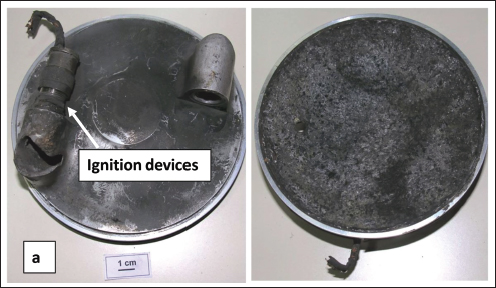
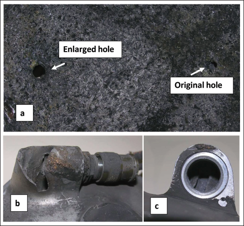
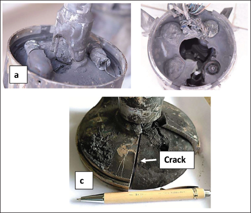
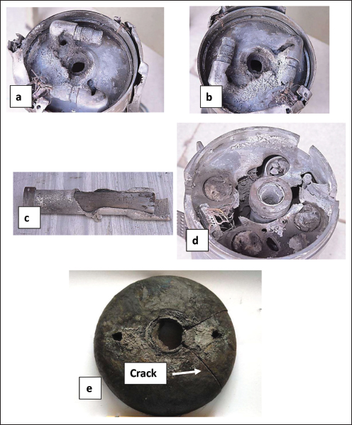
The failed booster head end of the pyro housing (PH-1) in the as-received condition is shown in Figure 1. Damage was observed to be due to an opening that occurred on the pyro housing where the pyro cartridge is fitted with an M16 threaded joint. Photographs showing the damaged, failed pyro housing, and intact pyro housing are presented in Figure 2. It is seen from Figure 2 that the damaged surface is very rough. The presence of several particles which solidified subsequently on the damaged surface can be noted. It is also noted that one hole is larger than the other one. The images of the damaged pyro housing (PH-2) of another anti-tank missile are presented in Figure 3. A part of the dome was found to be melted (Figure 3(a)). The rear wall was broken (Figure 3(b)), and the central hub was facing the pyro; with the loss of dome surface backing, the inner composite liner developed a crack (Figure 3(c)). The liner hole enlarged, and a crack was found to form in the liner hole. The photographs of the failed pyro housing of the third missile are illustrated in Figure 4. The liner is removed from the dome. Some deposition of molten metal can also be seen. Deposition of molten aluminium metal is shown in Figure 4. Part of the aluminium alloy casing of the blast tube melted (Figure 4(c)). The end wall of the flight is damaged (Figure 4(d)). A crack can be seen on the liner as well (Figure 4(e)).
Metallographic Examination
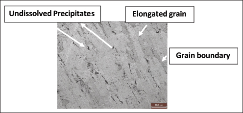
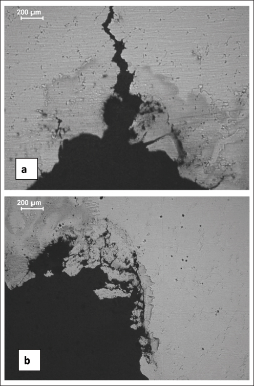
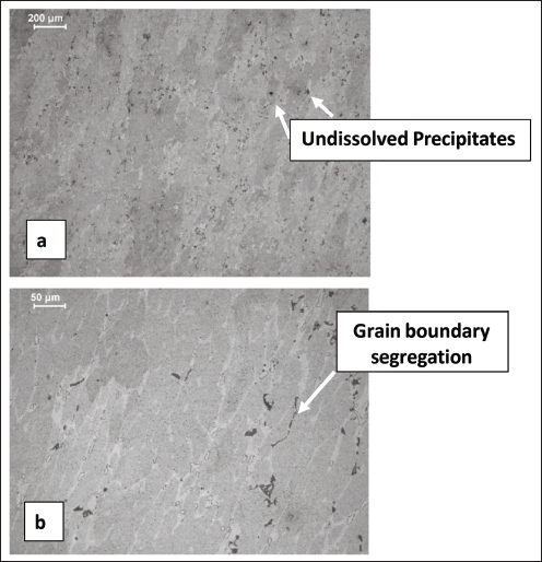
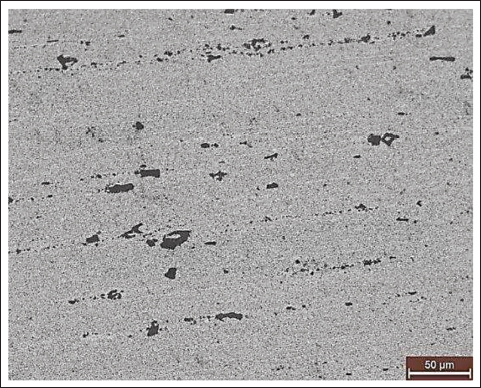
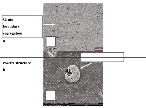
A representative microstructure of the metallic part of an intact pyro housing is provided in Figure 5. The material appears to be in solutionized, quenched, and aged condition. Al alloys, based on their composition, are solution treated between 500 °C and 550 °C for a few hours so that strengthening elements are fully dissolved in the matrix. This is followed by rapid quenching in water so as to make a supersaturated, unstable solid solution. Finally, the part is artificially aged between 150 °C and 180 °C to precipitate the hardening particles. This treatment results in an increase in strength and hardness. This treatment is referred to as ‘T6 heat treatment’ for Al alloys. In the unetched condition, the microstructure of PH-1 indicates the presence of a crack that was propagating from the fracture surface toward the inside, as illustrated in Figure 6. An optical micrograph of damaged parts of PH-1 is given in Figure 7. Figure 7 reveals that, on etching with Keller’s reagent, the microstructure reveals elongated grains and undissolved precipitates. Microstructures prepared from heat-affected zones of PH-2 and PH-3 are illustrated in Figure 8 and Figure 9, respectively. Although the heat-affected zone of PH-2 retained the original structure as shown in Figure 8, the microstructure of the heat-affected zone of PH-3 indicates grain boundary segregation and a rosette structure (Figure 9). These features confirm incipient melting of the material of PH-3.
Hardness Measurement
Vickers hardness was measured in the regions near the fracture surface and away from the fracture surface. The hardness is given in Table 1. The hardness of PH-1 is significantly higher in the region near the fracture surface than that in the region away from the fracture surface. Hardness of PH-2 and PH-3 compiled in Table 1 reveals that hardness of PH-3 is significantly higher than that of PH-2.
| Serial No. | Components | Location | Hardness (HV) |
| 1 | PH-1 | Near the fracture surface | 147 ± 4 |
| Away from fracture surface | 131 ± 4 | ||
| 2 | PH-2 | Near the failed surface | 79 ± 1 |
| Away from failed surface | 155 ± 5 | ||
| 3 | PH-3 | Near failed surface | 89 ± 1 |
| Away from failed surface | 155 ± 5 |
Note: PH: Pyro housing.
Chemical Analysis
The chemical compositions of all the pyro housings (PH-1, PH-2, and PH-3) were measured by instrumental analysis. The measured compositions of the damaged component are listed in Table 2. Compositions of all the investigated materials are more or less similar. The material is an Al-Cu alloy containing trace amounts of Si, Mn, and Fe.
| Components | Elements (wt%) | ||||||||
| Cu | Si | Mg | Cr | Fe | Mn | Ti | Zn | Al | |
| PH-1 | 4.65 | 0.33 | 0.42 | – | – | – | – | – | Bal. |
| PH-2 | 4.7 | 0.68 | 0.73 | 0.05 | 0.15 | 0.75 | 0.05 | 0.13 | Bal. |
| PH-3 | 4.47 | 0.6 | 0.71 | 0.05 | 0.2 | 0.7 | 0.05 | 0.12 | Bal. |
Note: PH: Pyro housing.
Fractographic Examination
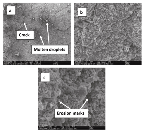
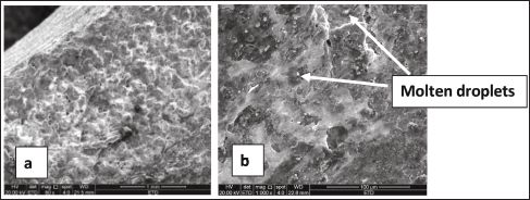
The failed sample was cut carefully not to damage the fracture features and ultrasonically cleaned in acetone. The scanning electron microscopy (SEM) fractography of PH-1 given in Figure 10 has shown eroded features with oxide coating. One fine crack is also observed on the fracture surface (Figure 10(a)). SEM micrographs of the failed surfaces of PH-2 and PH-3 are presented in Figure 11. Deposition of molten metal in some places can be noticed. Figure 11 also reveals a clean-cut area possibly obtained by gas cutting.
Discussion
It was informed that in PH-1, there are two pyro housings as an integral part of the booster head end, of which one has failed. The booster head end is an enclosure of the booster motor functioning for 1.4 s at a chamber pressure of 50 Ksc. The booster head end is designed to withstand a proof pressure of 90 Ksc and a burst pressure of 120 Ksc.
The chemical composition of the pyro housing indicates that the material is an Al-Cu-Si-Mg alloy and conforms to aluminium alloy HF15 grade (24345). The microstructure and hardness indicate that the material is used in the T6 heat-treated condition. No abnormalities in the microstructure were observed. Fracture surface examination of PH-1 indicates that the material has eroded from the inner surface to the outer surface of the housing. From the visual observations, it is seen that the pyro hole and the angle at which the groove is made are not the same in both pyro housings. The failed pyro housing has a more inclined angle and a longer groove length when compared to the other pyro housing, which is intact. This longer groove might have resulted in a reduction of the thickness of the housing. The reduction in thickness of the housing (PH-1) and the more inclined angle of the groove could not withstand the pressure developed during ignition. This results in the generation of subsurface and surface cracks, leading to the failure of the housing. The crack initiated at the triple point of the elongated grain boundary, which has significant segregation. A crack can be initiated at the interface of the undissolved precipitate and the matrix. These features are observed in the micrographs of the component (Figure 7). The elongated grains of the failed part indicate tensile stress in the direction of grain elongation. Surface cracks, which are also responsible for failure, are seen in Figure 6. Cracks are generated on the surface as the stresses are maximum on the surface.
The failed parts of PH-2 and PH-3 are made of aluminium alloy similar to that of PH-1, as revealed by composition analysis. The chemical composition, microstructure, and hardness are well within the specified range, as seen above. Therefore, material deficiency is ruled out as the cause of the failure. Signs of hot gas flowing between the liner and the aluminium dome can clearly be understood, as failed parts have features of damage by hot gas. This exposure to the super-hot gas might raise the temperature of the dome, causing loss of strength and subsequent failure of the pyro housing wall. Evidence of pyro housing (PH-2 and PH-3) leaking was noted. The hot gases are directed toward the blast tube of PH-2, resulting in the melting away of part of the dome and central hub facing the pyro, with the loss of dome surface backing; the inner composite liner developed a crack. The hot gases escaped from the last chamber by breaking the rear wall. The gas flow of PH-3 was directed toward the centre, melting away the aluminium alloy casing of the blast tube on one side up to half of the length. A small part of the dome surface was melted. The hot, high-speed gases made some holes in the rear wall of the last chamber and escaped. Some molten aluminium metal is seen deposited. The liner of PH-3 showed a pattern of gas flow from the pyro holes toward the centre. This flow occurred between the aluminium alloy dome and the composite liner. The leak was initially directed horizontally toward the centre and then became vertical due to erosion in the aluminium alloy wall. The quantum of gas flow in PH-3 is significantly higher than that in PH-2, resulting in alteration of the microstructure of PH-3 but not in PH-2. The gas flow left evidence of deposition of molten Al alloy, and higher gas flow in PH-3 gives rise to a clean gas-cut surface.
The domes of the pyro housings were made by closed-die forging and machining. They have two integral pyro housings and a central exit. The pyro housings have internal threads made by either machining or tapping. The central exit has outer threads to fix the blast tube. The rocket motor has an internal heat-resistant composite lining bonded with the aluminium alloy body with adhesive (Araldite). The dome has two oblique holes at 40° connecting the pyro housing internal volume with the rocket engine drilled through the lining and the dome wall. The rocket motor is ignited with both pyros firing simultaneously. The spark from the pyros travels through the 5-mm holes into the rocket motor, where it starts burning the solid fuel. The central exit has a tight-fitting graphite plug with a hole through which the hot gases move out, providing the required thrust. The exhaust gases travel through a cylindrical tube made of carbon-carbon composite up to the end of the missile through the control fin chamber. The C-C composite tube is held in place with an aluminium alloy tube threaded to the dome.
The missile has completed several successful trials without such failure in the past, implying there is no serious design or material problem. The dome in the beginning was made from bar stock that was later modified to closed-die forging. It should be noted that even the domes made from bar stock did not fail in this fashion. It does appear that deviation from the established manufacturing processes is the cause of the failure, specifically the bonding between the inner liner and the dome. The generation of cracks can take place at the triple-point boundaries of elongated grains with grain boundaries having significant segregation, weakening the grain boundary.
This type of failure can be avoided if an Al alloy with elevated temperature capability is used (Huang et al., 2024; Qian et al., 2008; Xue et al., 2023). The other option for improving performance is to coat the Al alloys with thermal-sprayed thermal barrier coating systems (Gokul Lakshmi et al., 2021; Malvi & Roy, 2021) or by coating a heat-resistant layer employing physical vapor deposition (PVD) techniques (Monfared & Dolati, 2026; Roy et al., 2020).
Conclusion
Detailed investigations to identify the cause of failure of pyro housings of three anti-tank missiles have been carried out.
Detailed analysis revealed that all the components of the propulsion system are made from aluminium alloy HF15 grade (24345) in the T6 heat-treated condition.
Metallurgical abnormality related to deviation from recommended material and composition or heat treatment cannot be noted.
The angle at which the groove is made is higher, and the grooves are deeper in the case of failed pyro housing than in the case of the pyro housing that was intact. This leads to a reduction in thickness and an increase in stresses, which, in turn, is responsible for the failure of the pyro housing (PH-1).
The manufacturing processes of the other two pyro housings (PH-2 and PH-3) were different from the recommended process. These components are manufactured by the closed-die forging process, which is a deviation from the original manufacturing process. This may be responsible for premature failure leading to a gas leak.
The cracks are initiated at the triple point of elongated grain boundaries, which have significant segregation leading to weakening of grain boundaries. A crack can be initiated at the interface of the undissolved precipitate and the matrix. These features are observed in the micrographs of the component. Subsurface cracks are seen in all three failed components. However, a surface crack was seen only in PH-1.
The authors declared no potential conflicts of interest with respect to the research, authorship, and/or publication of this article.
The authors received no financial support for the research, authorship, and/or publication of this article.
Bayraktar A., Hökelekli E., & Yang T. T. Y. (2022). Seismic failure behavior of masonry domes under strong ground motions. Engineering Failure Analysis, 142, 106749.
El–Mahdy D., Sameh H., & Fekry M. (2025). Structural stability of 3D–printed earthen catenary domes: Experimental and analytical insights. Structures, 81, 110273.
Foraboschi P. (2014). Resisting system and failure modes of masonry domes. Engineering Failure Analysis, 44, 315–337.
Gokul Lakshmi S., Malvi B., Rao D. S., Das D. K., & Roy M. (2021). Comparison of erosion rate of EBPVD and plasma sprayed TBC. Surface Engineering, 37(11), 1396–1403.
Huang J., Ando D., & Sutou Y. (2024). Heat–resistant aluminum alloy design using explainable machine learning. Materials & Design, 243, 113057.
Jha A. K., Kiranmayee M. S., Sreekumar K., & Sinha P. P. (2011). Failure analysis of M250 maraging steel stud used in flex nozzle control actuator bracket of solid propulsion system. Engineering Failure Analysis, 18, 1128–1133.
Jha A. K., Kiranmayee M. S., & Manwatkar S. K. (2013). Failure analysis of maraging steel fasteners used in nozzle assembly of solid propulsion system. Engineering Failure Analysis, 27, 308–313.
Kim T. G., Lee H., Choi J. M., & Hwang Y. H. (2005). Failure analysis of air interceptor missile rocket motors. Engineering Failure Analysis, 12, 307–315.
Madhav S., & Roy M. (2025). Analysis of failure of pin locator for internal nose cap of a long range cruise missile. Defence Science Journal, 75(5), 622–628.
Malvi B., & Roy M. (2021). Elevated temperature erosion of plasma sprayed thermal barrier coating. Journal of Thermal Spray Technology, 30(4), 1028–1032.
Monfared A., & Dolati A. (2026). Enhancing hardness in the ZrN/TiAlN superlattice coatings through modulation period optimization and interface control. Surface and Coatings Technology, 519, 132957.
Qian Z., Liu X., Zhao D., & Zhang G. (2008). Effects of trace Mn addition on the elevated temperature tensile strength and microstructure of a low–iron Al–Si piston alloy. Materials Letters, 62, 2146–2149.
Roy M., Saha S., & Valleti K. (2020). Microstructure and wear of cathodic arc physical vapor deposited TiAlN, TiCrN and n–TiAlN/–Si3N4 films. Defence Science Journal, 70(6), 656–663.
Schulz B. A., & Moran A. L. (2001). Fatigue failure of an F/A–18 fin retainer spring. Engineering Failure Analysis, 8(2), 167–172.
Xue H., Yang C., De Geuser F., Zhang P., Zhang J., Chen B., Liu F., Peng Y., Bian J., Liu G., Deschamps A., & Sun J. (2023). Highly stable coherent nanoprecipitates via diffusion–dominated solute uptake and interstitial ordering. Nature Materials, 22, 434–441.
